Table of Contents
Open Virtual Test Drive

Click the Windows start button, scroll to the “nVIZ” program group, click “Virtual Test Drive”.
Interface

- Each checkbox, if checked, will start a dedicated thread for the communication with one hardware device or software tool.
- The actual sampling rate for each thread will be displayed. For optimal performance of the overall system, it is important to tune the sampling rate of each hardware device and software tool to its individual optimal value.
- To analyze individual parameters or for debugging purposes, you can set a checkmark to create a log file of the complete communication on that thread. NB.: this will cost performance, i.e., should not be used in productive operation. The log files will be written to:
C:UsersPublicDocumentsnVIZVirtualTestDriveUserDataLogs - Use the Start and Stop buttons to launch all checked communication threads and to shut down all threads.
- The combo box provides the gear selection for automatic transmissions. The radio buttons allow you to switch the autopilot on or off for autonomous driving studies.

The digit displays show actual values of overall vehicle parameters while in operation.

The steering force, friction, and damping can be adjusted for an optimal steering experience while the server is running.

Each tab provides detailed settings for a communication thread.
The terminal window provides feedback, warnings and error messages. The messages are saved to a log file:
C:UsersPublicDocumentsnVIZVirtualTestDriveUserDataLogsVirtualTestDrive.log
Please send this log file to nVIZ if you encounter any issues.
Operating VTD Server with SENSO Wheel and IPG CarMaker

- Connect the SENSO Wheel and Pedals via the PEAK USB device to the host PC (make sure PEAK drivers are installed). Then turn on the SENSO Wheel.
- Launch IPG CarMaker.
- Load a Test Run.
- Click Application > Start & Connect to start the CarMaker APO server.
The CarMaker APO server needs to be running so that the VTD Server can connect to it. If the APO server is running, you will see the message “<hostname> online” in the CarMaker window header.

- In the VTD Server GUI …
- Check “Connect Simulation Solver”
- Check “Connect Main Controller”
- Click “Start” – the sample rates for the simulation solver and the main controller thread should switch to 50 Hz.
- In the CarMaker GUI…
- Click “Start” to start the Test Run – wait for the CarMaker state to switch from “Idle” to “Preparation” to “Running”
- In the VTD Server GUI…
- The time display should now show progressing time (same time as in the CarMaker GUI), the speed and distance displays will show zero while the vehicle’s gear selector is still in “P”, the rev display should show an engine idle rpm.
- Put the gear selector to “D”. The vehicle will start rolling, speed and distance should show the same values as CarMaker.

With the SENSO Wheel and Pedals, you can now drive the vehicle and experience your virtual test drive in the CarMaker Movie render window.
Operating VTD Server with Autodesk VRED or Unity

- For Virtual Test Driving in Autodesk VRED, see the documentation of the nVIZ Motion Plugin to understand how the VRED scene gets connected to the VTD Server.
- For Virtual Test Driving in Unity, see the nVIZ Unity Plugin Guide to understand how to connect your Unity project to the VTD Server.
- Repeat the steps outlined in the previous chapter but before you start the VTD Server, additionally check the “Connect Render Engine” checkmark to also run the render engine communication thread.
- With the SENSO Wheel and Pedals, you can now drive the vehicle and experience your virtual test drive in immersive, photo-realistic quality in your HMD or CAVE with VRED or Unity.
Simulation Solver
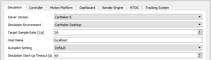
- Solver Version: The current release of VTD supports IPG CarMaker revision 5 and revision 6. For the support of other CarMaker versions and for the support of CarSim from Mechanical Simulation, please contact nVIZ.
- Simulation Environment: The vehicle dynamics simulation can be run in the CarMaker Desktop version or in the CarMaker for Simulink version.
- Target Sample Rate: The sampling rate needs to be tuned to achieve the best possible overall system performance. Setting the value too low will cause a juddering driving experience. Setting it too high will overload the PC.
- Host Name: Enter the name of the host PC running the simulation solver.
- Autopilot Setting:
- Default – the autopilot will behave like in most cars: it can only be switched on when the engine is running and will automatically switch off when the engine is turned off. It will also switch off when the driver takes an action (steering, braking, throttle).
- Constrained User Selection – The autopilot can be turned on before starting the engine (transmission selection needs to be “D”) and will remain on when the engine is stopped. It will switch off when the driver takes an action (steering, braking, throttle).
- Simulation Start-up Timeout: This is the time period after which “Start Simulation” request to Simulation Solver is expired. If the simulation model takes more time to load and start, then this value can be increased to provide some more time to simulation solver to start.
Main Controller – Steering Wheel and Pedals

- Main Controller: The current release of the VTD Server supports the force-feedback steering wheel and pedals of SENSO Drive.
- Target Sample Rate: The sampling rate needs to be tuned to achieve the best possible overall system performance. Setting the value too low will cause a juddering driving experience. Setting it too high will overload the PC.
- Steer Torque Gain: The force-feedback you experience on the steering wheel can be applied from two sources: A) The SENSO wheel’s steering model. B) The simulation solver’s steering model. And it can be a combination of both. The amount of forces applied to the steering wheel from the SENSO wheel’s steering model is defined by the sliders in the VTD Server GUI. These sliders can be set from zero to maximum. The amount of torque applied from the simulation solver’s steering model is defined by the “Steer Torque Gain” parameter. A zero value will not apply any torque from the simulation results, a value of 1 will apply 100% of the torque. Note: Applying the torque from the simulation solver requires the steering model, the tire model and the road model of the simulation solver to be correct! Incorrect simulation data could result in high torque values and cause injury!
- Steer Torque Limit: Set this value to limit the maximum torque on the steering wheel when experimenting with the Steer Torque Gain parameter.
- End Stops: Limit the maximum rotation angle of the steering wheel.
Note: Pedal Calibrations are moved to Preferences Dialog.
Auxiliary Controller

The Auxiliary Controller thread can be used to communicate with an arbitrary analog input device.
- Auxiliary Controller: Please contact us to have your specific device added.
- Target Sample Rate: The sampling rate needs to be tuned to achieve the best possible overall system performance. Setting the value too low will cause a juddering driving experience. Setting it too high will overload the PC.
Note: Pedal Calibrations are moved to Preferences Dialog.
Motion Platform

- Motion Platform: The current release of the VTD Server supports the COSMATE MB150 and Bosch eMotion 2700 motion platform. To have other platforms supported, please contact us.
- Target Sample Rate: The sampling rate needs to be tuned to achieve the best possible overall system performance. Setting the value too low will cause a juddering driving experience. Setting it too high will overload the PC.
- COM Port / UDP Port: Set the port number to which the platform is connected.
- Host IP Address (Only for Bosch eMotion): Set the IP address of the motion computer.
- Mode (Only for Bosch eMotion): Set the mode in which the data should be sent to the motion platform. In the engaged mode, the motion platform will move according to the instructions. However, in the neutral mode, the motion platform will stay at the null position and the Bosch Rexroth software can be used to observe the expected movement. The neutral mode should be used to fine-tune the motion cueing algorithm.
- Include X,Y,Z Translation / Roll, Pitch, Yaw Rotation: Set the checkmark for each degree of freedom to be communicated from the simulation solver to the motion platform or not.
- Use Custom DLL: To get the best possible driving experience from your motion platform, we deliver a custom DLL (C++) with the VTD Server installation which allows you to write your own motion cueing algorithm. Set the checkmark for any DOF to apply your own motion cueing algorithm.
Equilibrium State

The CarMaker solver will calculate the vehicle equilibrium state in the preparation phase and apply the transformations to put the vehicle into its state of equilibrium. Typically you will want to subtract these initial transformations so that the motion platform takes its initial position at the first simulation time step.
- Fr1 Origin X, Y, Z, Roll, Pitch, Yaw: Enter the six values of the CarMaker reference frame FR1 in the vehicle’s equilibrium state to have them subtracted from the initial transformations and keep the motion platform in its initial position at the start.
To get your vehicle’s equilibrium state values, open the CarMaker GUI, load the Test Run, go to Simulation > Model Check and click Start. You will get a text file in the editor. At the bottom of the text file, you will find the corresponding values under the header line “###Geometry (equilibrium or start-off configuration)”.
Driver Hip Point

The transformations received from the CarMaker solver are all given in the FR1 CarMaker reference frame. The FR1 is located in the vehicle’s symmetry plane, at the most rear point of the vehicle, on the ground. For a correct driving experience on the motion platform, these values need to be transformed to the driver hip point and then applied to the motion platform.
The translational accelerations are required for the motion cueing algorithms of Bosch eMotion motion platform. These accelerations received from CarMaker solver are in FR1 CarMaker reference system at the center of gravity. All these values need to be transformed to the driver hip point before being applied to the motion platform.
We assume that the motion platform’s controller makes sure the received rotations apply to the hip point of the person seated on the motion platform.
- Hip Point X,Y,Z: Coordinates of the driver’s hip point in the CarMaker FR1 reference frame.
- Center of Gravity X,Y,Z (Only for Bosch eMotion): Coordinates of the center of gravity of the car in the CarMaker FR1 reference frame.
Motion Cueing X-DOF and YAW-DOF Algorithms

These settings are only available for COSMATE motion platforms. Accelerations exerting forces on the driver’s body are usually called motion cues. The limited workspace of the motion platform makes it impossible to generate long lasting acceleration cues but special motion cueing algorithms can compensate this limitation to some extent. The plugin includes motion cueing algorithms requested by a customer for the X-DOF and the YAW-DOF. To get the best possible driving experience from your specific motion platform, use the custom DLL we provide with the installation to develop your own motion cueing algorithms or contact us to have your algorithms added to the GUI.
- X-DOF Algorithm
- Osato I: X-DOF = Car_ax * OsatoIFactor1 * OsatoIFactor2 * XDofGain
- Osato II: X-DOF = ValuePreviousTimestep * (1.0 – OsatoIIFactor3) + OsatoIIFactor3 * Car_ax * OsatoIIFactor1 * OsatoIIFactor2 * XDofGain

- YAW-DOF Algorithm: YAW-DOF = Car_SideSlipAngle * -1.0 * YawDofGain
Dashboard

- Target Sample Rate: The sampling rate needs to be tuned to achieve the best possible overall system performance. Setting the value too low will cause a juddering driving experience. Setting it too high will overload the PC.
- UDP Port 1: Communication port. Change the number in case that port is being used by some other application.
- UDP Port 2: currently not used.
Render Engine

- Render Engine: Currently supported: Autodesk VRED and Unity
- Target Sample Rate: The sampling rate needs to be tuned to achieve the best possible overall system performance. Setting the value too low will cause a juddering driving experience. Setting it too high will overload the PC.
- UDP Port : Communication port. Change the number in case that port is being used by some other application.
Real-Time Operating System

For time-critical simulation, data acquisition and process control applications you can have VTD Server communicate with a real-time operating system.
- RTOS System: VTD Server supports the iHawk system of Concurrent.
- Target Sample Rate: The sampling rate needs to be tuned to achieve the best possible overall system performance. Setting the value too low will cause a juddering driving experience. Setting it too high will overload the PC.
- UDP Port : Communication port. Change the number in case that port is being used by some other application.
- Send to RTOS: Type in any CarMaker quantity to be communicated to the RTOS.
- Receive from RTOS: The number of quantities in the list must match the number of quantities received to that port from the RTOS. Type in the CarMaker quantity to which you want to have the received value assigned and a default value, separated by comma. The default value will be assigned to the CarMaker quantity until the RTOS delivers data.
Preferences

Preferences dialog can be found under ‘Edit’ in the VTD Server GUI. It contains some of the settings that are not expected to be changed very frequently. It contains settings of the pedals and the motion rotation point of motion platform among many other settings. To get the live analog value of the pedals in the preferences dialog, the server must be started and the respective controller must also be checked.
‘Save’ button can be used to save the preferences to the file which will be loaded every time the application starts. ‘Cancel’ button will just close the preferences dialog without saving the changes. ‘Restore Defaults’ button can be used to load back the factory settings. The user preferences are saved to the preferences file under:
- C:UsersPublicDocumentsnVIZVirtualTestDriveVTDserver.pref

General
Server – Log File Allowed: Set it to “True” if the data communication between the VTD server and different hardware/software components needs to be logged. However, if you want to reduce the CPU power being used by the VTD server, set it to “False”. With this option being false, log file check buttons will be disabled in the GUI.

Main Controller
- Wheel Forces: Set these six parameters to control the range of the sliders (min, max values) in the VTD GUI. The sliders will set the SENSO wheel’s steering model forces.
- Pedals Calibration: The pedals need to be calibrated occasionally. Follow these steps:
- Release the throttle pedal.
- Read the “Analog Input” value.
- Type in that value as “Minimum”.
- Push the throttle to its max.
- Read the “Analog Input” value.
- Type in that value as “Maximum”.
- Repeat the six steps above for the brake and clutch pedal.

Auxiliary Controller
- Pedal Calibration: The device needs to be calibrated occasionally. Follow these steps:
- Release the device.
- Read the “Analog Input” value.
- Type in that value as “Minimum”.
- Push the device to its max.
- Read the “Analog Input” value.
- Type in that value as “Maximum”.

Motion Platform
MRC X, Y, Z: Set the values of the seat reference point (SRP / MRC) from the motion rotation point (MRP) of the Bosch eMotion platform. MRP of motion platform should be defined in the documentation provided by Bosch Rexroth.